illyshop
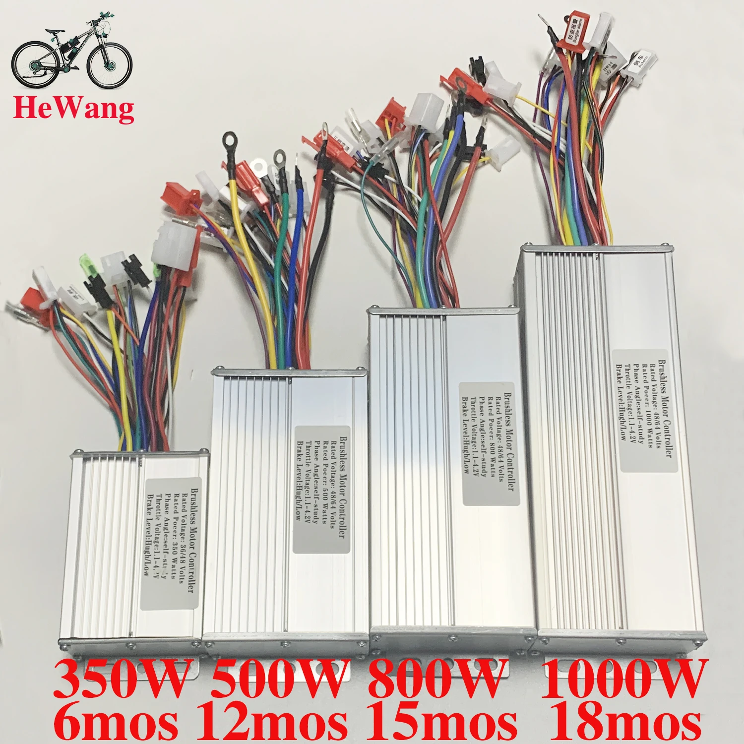
48V 64V 350W/500W/800W/1000W E-bike Square Wave Dual Mode Brushless Motor Controller with Self-Learning Wire for Ebike Scooter
48V 64V 350W/500W/800W/1000W E-bike Square Wave Dual Mode Brushless Motor Controller with Self-Learning Wire for Ebike Scooter
Couldn't load pickup availability
SPECIFICATIONS
1000W: 350W
48V: 64V
500W: 800W
Choice: yes
Brand Name: NONE
Origin: CN (Origin)
Highly concerning chemical: None
Type: Controller
brushless motor: controller
for: Electric bicycle,scooters battery cars,three-wheel electric vehicles
square wave dual mode: controller
with: self-learning line
48V/64V 350W/500W/800W/1000W Square Wave Dual Mode Electric Bike Controller, Brushless Motor Controller with Self-Learning Line for Scooters, Battery Cars, Three-Wheel Electric Vehicles
350W 48V-64V 6 months
Voltage: 48V/60V/64V
Rated Power: 350W
Current: 15-18A
Case Dimensions: 10*6.5*3.3 cm
MOS Tube: 6 mosfets
500W 48V-64V 12 months
Voltage: 48V/60V/64V
Rated Power: 500W
Current: 30A
Case Dimensions: 15*8.5*4 cm
MOS Tube: 12 MOSFET
800W 48V-64V 15 months
Voltage: 48V/60V/64V
Rated Power: 800W
Current: 35A
Case Dimensions: 18.5*8.5*4 cm
MOS Tube: 15 mosfets
1000W 48V-64V 18 months
Voltage: 48V/60V/64V
Rated Power: 1000W
Current: 45A
Case Dimensions: 21*8.5*4 cm
MOS Tube: HY3412, 18 mosfet
350W 48V-64V 6 mos line diagram
1. Power cord
2. Learning cord
3. High-level brake
4. Anti-theft power supply
5. Low-level brake
6. Hall line
7. Turn handle line
8. Cruise line
9. Anti-theft alarm
10. Three-speed transmission
11. LCD instrument
12. Motor line
13. Motor line
14. Motor line 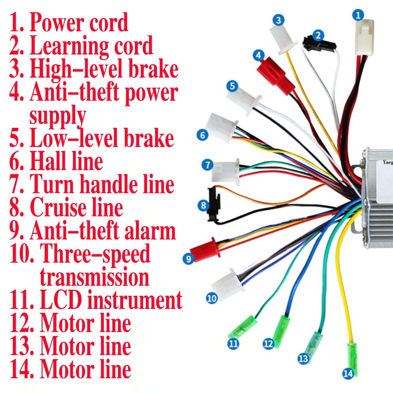
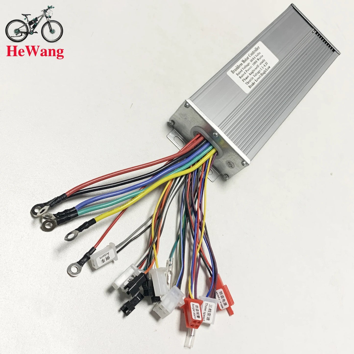
(500W 48V-64V 12 mos 800W 48V-64V 15 mos, 1000W 48V-64V 18 mos) Line Diagram
1. Electric door lock key line
2. Power line positive line
3. Power line negative line
4. Reverse line
5. LCD instrument line
6. Three-speed transmission line
7. Cruise line
8. Cruise line
9. Stepless three-speed adjustment button
10. Throttle cable
11. Motor Hall line
12. Anti-theft alarm line
13. Battery high voltage brake line
14. Battery low brake line
15. Learning line
16. Learning line
17. Hall pointer instrument line
18. Motor line
19. Motor line
20. Motor line 
No. 1
Connect three motor wires. (Motor wires have no positive or negative poles and can be connected arbitrarily.) Connect the three controller wires to the three motor wires of the electric vehicle.
No. 2
Please connect the power cord (thick red wire for positive pole, thick black wire for negative pole) and the switch lock wire (thin red wire) of the controller to the positive and negative poles of the electric vehicle's power supply, respectively.
No. 3
Learning line First, please insert a pair of white learning wires from the controller together, then plug in the power key and turn on the power to observe whether the motor rotates: 1. If the motor rotates forward, it indicates that learning is complete, please unplug the learning wires; 2. If the motor rotates in reverse, unplug the learning wire and reinsert it. Wait until the motor rotates forward before unplugging the learning wire.
No. 4
Hall line This product has 5 connecting wires and one connector for the Hall wire.
If there is a shaking sensation when connected to the Hall, it indicates that this product can start without Hall. If the motor's Hall (sensor) is damaged, it is recommended not to connect the Hall.
No. 5
Please connect the handle wire of this controller (the red wire is the positive pole, the black wire is the negative pole, and the green wire is the signal wire) and the handle wire of the electric vehicle accordingly.
After completing the above five steps, the electric vehicle can operate normally.
Please install other required functions by yourself.
No. 6
Purple high and low level fine brakes The controller has both a separate yellow line for high-level braking and a black and white line for low-level braking. High-level braking and low-level braking are distinguished by braking voltage. If the braking voltage exceeds 5V, high-level braking is used. If the braking voltage is lower than 5V, low-level braking is used. Both high and low levels have the effect of power-off braking.
No. 7
Instrument line The instrument cable is a separate thin green wire, suitable for pointer-type instruments. If it is an LCD instrument, please choose carefully, as there may be incompatibilities.
No. 8
Patrol routes Cruise control is divided into automatic cruise control (inserting the cruise line is sufficient) and button cruise control (two buttons come out and are connected to the cruise line)
No. 9
Connected to a three-speed line. The three-speed line is blue-brown-black, with blue and black short circuits indicating high speed, brown and black short circuits indicating low speed, and electric vehicles defaulting to medium speed.
No. 10
Connected to the anti-theft alarm function. The anti-theft function line consists of two sets of cables: anti-theft power and anti-theft signal. Among them, the red and black lines of the anti-theft power represent the positive and negative poles of the battery, while the red line of the anti-theft signal represents the switch lock wire, the yellow covering represents the wheel signal wire, and the blue line represents the anti-theft signal wire.
No. 11
Reverse function The reverse function is a closed circuit that can be replaced according to your own needs. Short-circuit the black and gray lines of the reverse window line to reverse.
No. 12
LCD instrument